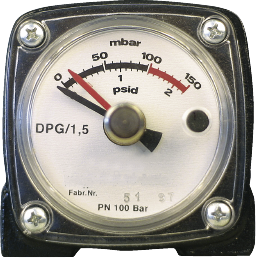
The differential pressure gauge type DPG is a measurement device for monitoring the pressure difference at filters, traps, etc.
Differential pressure between entrance and exit is brought up onto a display by a diaphragm measuring system on a clock face.
Contrary to the well-known rotary gas metering system, this system is not prone to construction-related leakages. Model type DPG is 100% leak-proof and can be tested (static) with a measurement kit.
Loosen the Allen screw. Next, the magnet socket with the DIN-reed contact plug can be slid into the housing or pulled out:
=> sliding in: earlier switch point
=> sliding out: later switch point
After the switch point has been set – recommended is the last third of the scale length – the magnet socket is secured with the fixing screw (Allen screw).
1. Installation / Manifold / Valve register
Differential pressure gauge type DPG can be complimented with a valve register (manifold). This valve register offers the following mounting advantages:
a) Performing the minus connection is made at the rear side of the valve
register. The plus connection can be made either at the left or at the right. This avoids crossing of the measurement leads and the positioning of special versions of the basic unit.
b) Pressure compatibility between (+) and (-) via knurled screw (1) in the middle of the valve register (e.g. run-up, for checking the 0 display during operation).
c) Using both of the screws (2) O-ring sealed valves can be closed. Differen- tial pressure gauge type DPG can then be removed problem-free from the valve register (e.g. for checking, exchanging, etc.).
d) The valve register (manifold) contains both valves i.e. block ball-valves, which are otherwise necessary for mounting.
e) Additionally, a filter cartridge can be screwed into the valve register (manifold) to protect the measurement mechanism.
f) Maximum operating pressure for the valve register (manifold): 102 bar Weight: valve register/manifold: 850 g
2. Switching contacts
There are 3-pole reed contacts available, electrical capacity: 3 VA/28 V / 0.25 A. For operation in an ex-zone- electrical separation is necessary via approved ex-relay.
3. Filter cartridge
Instead of screwing-in the valve block, a filter combination with sinter metal insert can be added.
This filter combination prevents the penetration of contaminants into the measurement mechanism.
Weight: filter: 160 g
4. Fixing bracket
A fixing bracket with the necessary spacer sleeves and bolts is available for stable fitting to a filter or a sign gantry.
5. Features
| Bypass and shut-off valves: |
integrated (checking the “0 display“ in operation possible) |
| Mounting: |
right-left or left-right |
| Screw-in filter: |
addable |


